Recasing the PSU of the Sony Playstation SCPH100x

by Mick Feuerbacher, June 2006.


The PS1 is equipped with a switch mode power supply (SMPS), which is placed in the left part of the case, below the power and reset button. This compact arrangement has a number of disadvantages, which may limit the sonic performance of the PS1 if used as a CD player. First, in the stock form, the PSU may heat up the whole PS1 considerably. Second, particularly at the end of a CD, the laser unit comes into close distance of the SMPS. This may cause that stray signals are picked up by the laser electronics. This article describes a procedure for recasing the SMPS into a separate box.


A: The PSU side

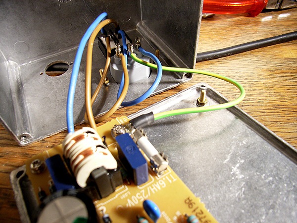
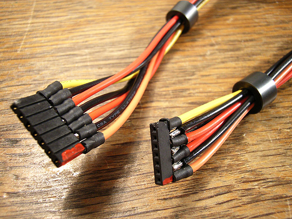
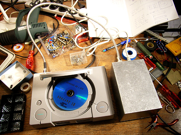
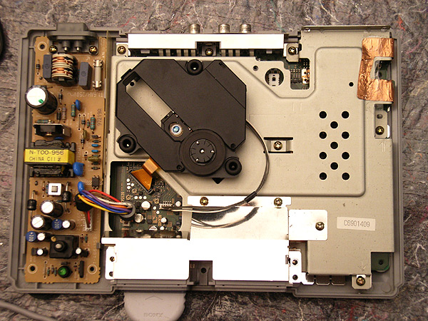
Disconnect the PS1 from the mains and open the case (five black screws on the bottom). The SMPS is the brown board on the left hand side. It is connected to the main board by a seven-pole cable.

Remove the cable and the two screws at the mains connector. Then take the board out of the case.


Desolder the two-pole mains connector on the PSU board.


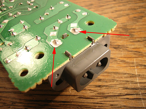
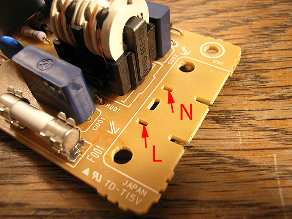
You can use the corresponding holes on the top side of the board to make your new mains connection. The N and L (the latter goes through the fuse) connections are marked on the picture.


Select a case of appropriate size. Add a switch and a mains connector and wire everything correctly. You don' need to add a fuse, as there is already one on the board.

Make sure that you connect a safety earth to the case. I have connected the mains earth to the case through one of the screws attaching the board to the case. If you do so, make sure that you use a conducting spacer. Check if there really is a connecting between the ground pin of the mains connector and the case!

Before you close the case, set the power switch on the PSU board to "on" ;-)


B: Cables

The pinout of the connector on the PSU board is as follows:

1: 7.6 V
2: 0 V
3: 3.6 V
4: 0 V
5: 3.6 V
6: 0 V
7: reset

On the PSU board as well as on the main board of the PS1, pin 1 is the lowermost pin when the PS1 is oriented as shown in fig 1.

I decided to use a seven-pole umbilical cable. This is not absolutely necessary - you may reduce the number of poles for the connector to five be joining all grounds or even to three by additionally joining the 3.6 V lines. You can safely omit the reset connection. However, I had seven-pole DIN connectors and a cable at hand, so I followed the original connection scheme.


Then you have to make two connector cables between the boards and the power jacks. On the board side, you can either directly solder the cables to the pins, or, in order to be more flexible, make some pluggable connections. To use the stock connectors is a very fiddly job, so I decided to use standard flat-cable connectors as used in computers.


The pin spacing on the PSU board is 2.5 mm (1/10 inch) and on the mainboard it is 2 mm. For both spacings, flat cable connectors are available. Cut them to size and solder them to the cables.
This is a close up of the board sides of the connectors. Note that I have marked pin 1 with some red paint. On my boards, pin 1 is also marked in red. This is to avoid plugging in the cable the wrong way round, which may damage the PS1.


C: The drive side


The connection on the drive's side, i.e. in the PS1 case, is straightforward and can best be made in the position of the former mains connector.


Enjoy....